History of FlightI will bring you only some of History that I think it is useful for you to know about how the helicopter was developed. They were so many great people contributed to this technologies but some of them were succeed and some were not. We all thanks to those people which make today happen.
Igor Sikorsky (United States) It was during 1909 that Igor Sikorsky Build his first machine in Russia in common many earier designed. But this first Sikorsky helicopter never left the ground, and a second which followed in 1910 ,he did not succeeded at this time so, he stopped and turn to fixed wing aircraft until 1930 .
VS-300: In 1939, Sikorsky and a team of his engineers desinged the VS-300. The VS stood for VoughtSikorsky and the 300 indicated that it was Sikorsky's third helicopter design.Vs300 had a75 hp Franklin 4cylinder engine. The basic structure was the heavygauge welded steel tubes. It had no covering at all and no instruments.It had three bladed main rotor and the anti-torque rotor at the rear.
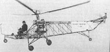
VoughtSikorsky VS-300 The R-4: In 1941, Sikorsky and Gluharaff designed the production model of VS300 and desinated VS316A . It was the bigger a bigger machine with an enclosed cabin and side by side seating and dual controls for two men crew 175 hp engine, a larger 36 ft (10.97 m.) rotor.The VS316A known by military designation XR-4 and YR4A.

VS-316A The R-5 and S-51: In 1943,Sikosky was working on all metal designated VS327 to meet requirement of USAAF known as XR5S and YR5A. It was better and bigger than R4.
In 1946, the first civilian type helicopter,S51 (four seats) was the first helicopter to be licenced by the US Civil Aviation Administration for commercial operation.

Sikorsky S-51 The S-55: In 1949, Sikorsky S-55 was located 600hp engine in the nose. For the first time, a helicopter was capable of lifting a heavy load up to ten soldiers,in addition to its two men crew.

Sikorsky S-55 Focke Achgelis Fa61 (Germany) Fa-61: Germany stepped to the front in helicopter development with the Focke Achgelis Fa-61, which it has two three-bladed rotor mounted on outriggers and power by a 160 hp radial engine. The Fa-61 had controllable cyclic pitch and set many of records .
In 1938, Fa-61 made an altitude flight of 11,243 feet and cross-country of 143 miles.In this year, the german aviator Hanna Reitsch became the world's first woman helicopter pilot by flying the Fa-61 in the Deustchland-halle in Berlin. Germany continued its helicopter development during world war two and was the first to place the helicopter,Flettner Kolibri, into mass production.

Focke Achgelis Fa-61 Jaun de la Cierva (Spain) / Autogiro Cierva C30A : An Autogiro, in 1923 , Juan de la Cierva , a young engineer made the first successful flight of an autogiro. An autogiro operates on a different principle than a helicopter.That was the rotor of autogiro was not driven by the engine but rotated itself as the aircraft was drawn along by its propeller. Autogiro used extreamely short take-off and landing but it could not move sideways or hover in still air like a helicopter. The Autogiro's rotor is designed so that a blade set at a low positive angle of pitch will rotate automatically as long as an airstream is kept flowing through the rotor .However, the technology of the rotor head and the rotor blade developed for autogiro contributed importantly to the development of the successful of helicopter.

Cierva C30A Lawrence Bell (USA) Bell Model 30 :Bell Aircraft Corporation was formed in 1935 but it was until 1943 that the first Bell Helicopter Model 30 was successful flown. Several version of model 30 were built . Model 47 , built in 1945 and was granted the world's first commercial helicopter licence. The Bell 47 developed into the most successful light - utility helicopters ever. A total of morethan 6,000 variants were built until the production was stopped in 1973


 This type of flying machine utilizes the flapping of the wings in order to achieve flight. Needless, is to say that all attempts to fly using this type of machine failed.Machine lighter-than-airIn the year between 1650 and 1900 , there was a second attempt at flying with a less sophisticated but more efficient generation of flying machines, the lighter-than-air craft. The idea of filling a closed container with a substance that normally rises through the atmosphere was known as early as the thirteen century. Over a five hundred year span, different substances came to be known as being lighter-than-air. The most common gas proposed was water vapor, helium and hydrogen. The first successful attempts at achiveing flight using his type of crafts were made by the Montgolfier brothers in France. Their most successful attempt was in 1783.
 The most successful builder of this type of lighter-than-air craft was Count Ferdinand von Zeppelin (picture above) . In the early 1930's the German Graft Zeppelin machine was able to make a Trans-Atlantic flight to the United States. The large Hidenburg was equally successful until it was destroyed by fire while attempting a landing in 1937 at Lakehurst,New Jersey.Orville and Wilbur WrightIn the early 1900s two American brothers, Orville and Wilbur Wright from Dayton, Ohio began to experiment with gliders. The gliders were built using data from Otto Lilienthal in Europe. Most of these flights turn out to be a failure. In 1901, they decided to gather their own wing data by conducting systematic experiment on different type of wing configurations. In 1902, Glider has wingtip to wingtip measurement of 32 ft. and wing width of 5 ft. This was the first aircraft with three-axis control. This mean that the aircraft could go up or down, left or right, and could also roll about its longitudinal axis. At Kitty Hawk, they perform over 800 flights, the early problem of aircraft were solved .
 The Wright brothers, now confident about their ability to flight, decided to turn their attention to power. In 1903, after redesigning the airframe of their 1902 glider, the Kitty Hawk Flyer was born. In December 17 , 1903 , with this aircraft, Orville and Wilbur Wright demanstrated the flight of self powered aircraft.Bleriot XI Monoplane
 The future potential of the airplane was realized when Louis Bleriot (France) flew his XI monoplane across the Einglish Channel in 1909. This was made Britain could no longer feel secure because England rely only on the royal navy.Henri Fabre SeaplaneThe first Seaplane was built and flown by Henri Fabre (France) in 1910 at Martigues, France. The great pioneer of marine flying was Glen Curtiss of the United States. In 1911 he fitted floats to his pusher biplanes and flow it off the water.
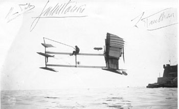 First flight of a seaplane called a Hydravion was created by Frenchman Henri Fabre. Using a 50 horsepower Gnome rotary engine, Fabre flew 1650 feet on water (March 28, 1910).Vikers Gunbus:
 Until 1914 , As the war progressed, the manufacturers were pressed to equip airplanes with guns, bombs and torpedos. This Vicker Gunbus (England) had been accomplished by 1914.F.X. Trimotor:
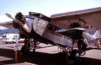 From the United States, Ford Trimotor is the world's first airline services were in 1910. With the advances in aircraft designed brought about by war, the enclosed cabin airplane became the standard for commercial airline travel by the early 1920's.As the time went by, the speed of airplanes began to increase. From the famous 12 mph top-speed of Wright Brithers Kitty Hawk Flyer , until in 1947, a test pilot named Chuck Yeager flied exceeded the speed of sound. From that point on a series of experimental supersonic aircraft took to the sky breaking speed record after speed record. Today we still can see some of supersonic aircrafts that were built in the 1960's like Concorde(mach 2), TU-144 (mach 2.2), SR-71 Blackbird (mach 3).


 Aircraft Flight Control
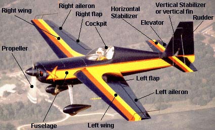

 FLIGHT DIRECTIONAL CONTROL THE AXES OF ROTATION


 Main Rotor
 Dissymmetry of Lift
  Blade Flapping
 Anti torque Pedals


